EzSBC
ESP32 Breakout and Development Board
ESP32 Breakout and Development Board
Couldn't load pickup availability
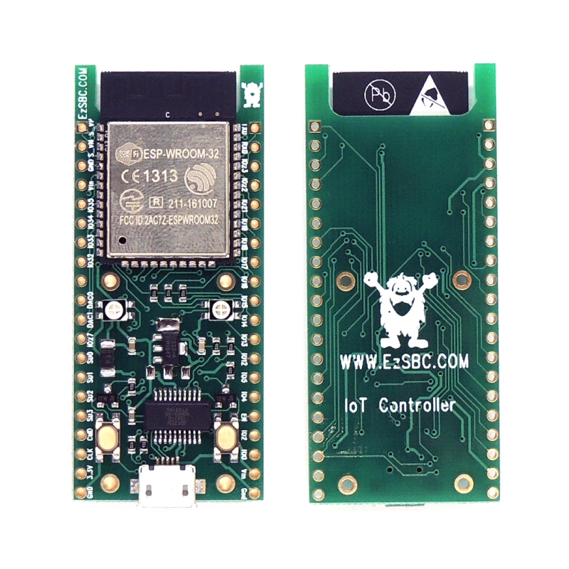
ESP32U-01 Breakout and Development Board with 10uA sleep current.
ESP32U Dev Board WiFi+Bluetooth with Internal Antenna, USB to Serial. Arduino Programmable. Designed and Made in the USA
This is our top selling ESP32 development board. Made in and ships from the USA. Other than the ESP32E module it has (an Si Labs CP2104) CH9102F USB to Serial converter, A 3.3V LDO, Reset and Flash Switches and a multi color LED.
The board uses the latest ESP32-WROOM-32E module that has an integrated antenna on the PCB.
There are two tri-color LEDs on the board. One has the red and green LEDs hooked up to the FT231 to signal transmit and receive activity and the other is connected to three IO pins on the ESP32 module.
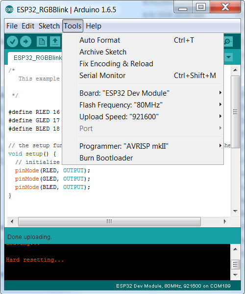
The board supports auto-download from the Arduino environment and will automatically be set in download mode by the downloader. Once the download is complete the board will be reset, just like a normal Arduino board.
All the required capacitors and pull-up resistors are fitted on the board. The board can be powered from an external power supply of up to 1̶2̶V̶ 8V or the USB connector or both. The low quiescent current LDO had the specification revised to a maximum of 8V instead of the 12V in the previous revision of the datasheet.
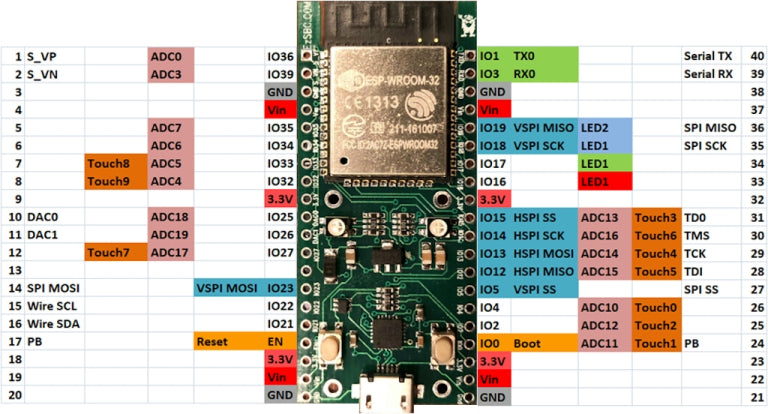
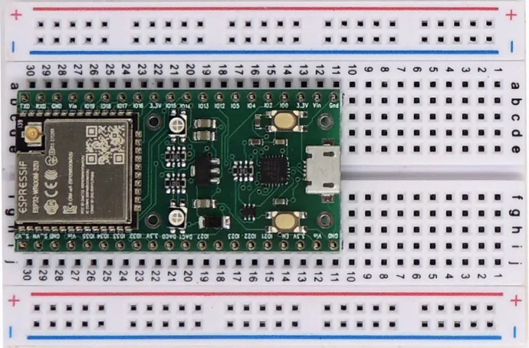
Unlike most other boards this one fits on a breadboard and has one row of pins accessible on each side of the board. Most of the pins of the ESP32 module are available on the external pins.
The module can be programmed directly from the Arduino environment without pushing any buttons. The upload speed is 921600 bps.
The module has been designed to be used in Sleep mode without excessive current draw. I read 9uA when powering from the Vin and Gnd pins.with the processor in deep sleep mode. By removing Schottky Diode another few uA can be saved but then the board must be powered by the Vin pin while programs are downloaded.
https://github.com/grillbaer/esp32-power-consumption-test has a comparison of Deep Sleep current consumption for a few different ESP32 boards. This board has the lowest current use of the boards in the comparison.
Additional documentation such as the schematic and demonstration code is available here: https://github.com/EzSBC/ESP32_Dev
- 240 MHz dual core Tensilica LX6 microcontroller with 600 DMIPS
- Integrated 520 KB SRAM
- Integrated 802.11BGN HT40 Wi-Fi transceiver, baseband, stack and LWIP
- Integrated dual mode Bluetooth (classic and BLE)
- 4 MByte flash
-
2.2V to 3.6V operating voltage3.6V to 5.5V on Vin, 3.0V to 3.6V driving the 3.3V pin directly. - On-board PCB antenna
- 3 x UARTs, including hardware flow control
- 3 x SPI
- 2 x I2S
- 12 x ADC input channels
- 2 x DAC
- 2 x I2C
- PWM/timer input/output available on every GPIO pin
- SDIO master/slave 50 MHz
- Supports external SPI flash up to 16 MB
- SD-card interface support
- 8V Maximum input voltage
The datasheet of the ESP32 is misleading. It claims 2.2V to 3.6V operation and this may be true for the chip by itself its certainly not true for the chip and the Flash memory combination. The flash memory needs a minimum of 3.0V to operate.


