EzSBC
ESP32_Bat_Pro Battery Charging Breakout and Development Board
ESP32_Bat_Pro Battery Charging Breakout and Development Board
Couldn't load pickup availability
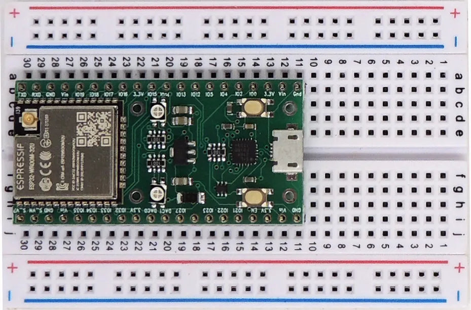
ESP32U-01 Breakout and Development Board with LiPo Charger
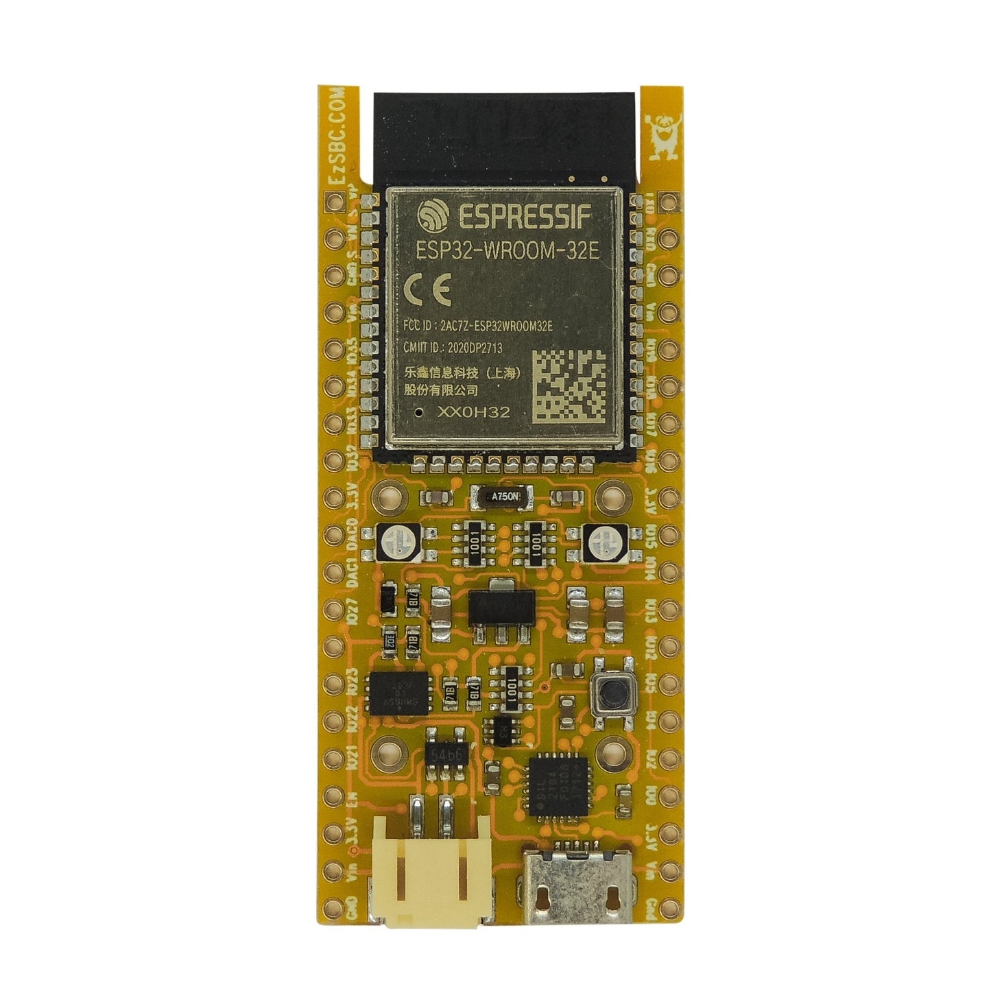
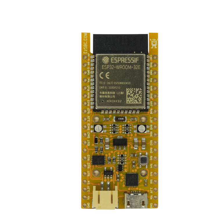
ESP32 Development Board with Onboard LiPo State of Charge Monitor, LiPo Charger, USB to Serial. Arduino Programmable. Designed and Made in the USA
This board is a superset of the ESP32_Bat board. It contains all the circuitry to charge and monitor a LiPo cell. The board has a LC709203F fuel gauge integrated and a good driver is available on the GitHub page. The LC709203F is permanently attached to the LiPo cell and can monitor the state of charge with very low drain on the cell.
The LC709203F ‘s algorithm eliminates the use of a sense resistor and provides accurate State of Charge (SOC) information even under unstable conditions e.g. changes of battery, temperature changes, loading, aging of the cell and self-discharge. Over time the algorithm updates its parameters to more accurately reflect the SOC of the cell. The algorithm does not use Coulomb counting so there is no build up of errors over time.
The cell monitor can cause an interrupt when the SOC reaches a value that can be adjusted in software or it can cause the interrupt based on the cell voltage. The interrupt output of the LC709203F is connected to IO19 of the ESP32 and is also available on the board connector. The interrupt can wake the ESP32 from deep sleep. The LC709203F is connected to the I2C bus and appears at address 0x0B. The driver published on the GitHub page will correctly initialize the SOC device.
The LC709203F contains two different cell profiles and models for cells of 100mAh, 200mAh, 500mAh, 1000mAh, 2000mAh and 3000mAh capacities. In the driver I have defined a number of constants to select the cell capacity and the nominal and maximum charge voltage of the cells. It is extremely important to choose the correct nominal and maximum cell voltage for the cell or the SOC will not be correct. For the cells sold here the LC709203_NOM3p7_Charge4p2 is the correct selection. This is also true for most of the rectangular LiPo cells sold elsewhere.
The board contain the usual CH9102F USB to Serial converter, A low quiescent current 3.3V LDO, Reset and Flash Switches and a multi color LED.
The Deep Sleep current is less than 12uA from the cell with the LC709203F active. I believe that this is the best solution available on the market.
There are two tri-color LEDs on the board. One has the red and green LEDs hooked up to the CH9102F to signal transmit and receive activity and is powered from the USB connector. The other tri-color LED is connected to three IO pins on the ESP32 module.
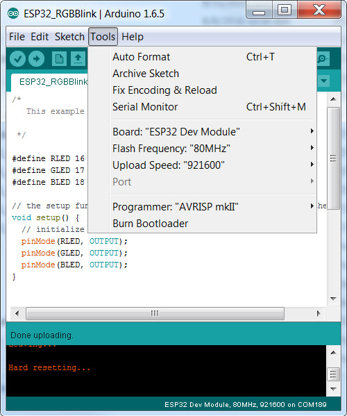
The board supports auto-download from the Arduino environment and will automatically be set in download mode by the downloader. Once the download is complete the board will be reset, just like a normal Arduino board.
All the required capacitors and pull-up resistors are fitted on the board. The board can be powered from an external power supply of up to 6V or the USB connector or both.
When external power is present the cell is charged with a 400mA charge current to a 4.2V cutoff voltage.
When the external power is present and the cell discharges the cell will automatically be re-charged.
An LiPo cell must be connected to the battery connector for the board to operate correctly as a WiFi transmitter. The peak current during WiFi transmission may exceed the current available from the charger.
Boards purchased without a cell will receive the matching charge cable.
The Cell connector is a JST2R commonly used on LiPo cells.
Unlike most other boards this one fits on a breadboard and has one row of pins accessible on each side of the board. Most of the pins of the ESP32 module are available on the external pins.
The module can be programmed directly from the Arduino environment without pushing any buttons. The upload speed is 921600 bps.
The module has been designed to be used in Sleep mode without excessive current draw. I read 12uA when powering from the Vin and Gnd pins.with the processor in deep sleep mode.
The overall dimensions and pinout is identical to the other ESP32 boards on this site.
The board uses the latest ESP32-WROOM-32E module .
The schematic is available here.
- 240 MHz dual core Tensilica LX6 microcontroller with 600 DMIPS
- Integrated 520 KB SRAM
- Integrated 802.11BGN HT40 Wi-Fi transceiver, baseband, stack and LWIP
- Integrated dual mode Bluetooth (classic and BLE)
- 4 MByte flash
- 3V to 6V operating voltage on the Vbat terminals if the battery is not used
- On-board PCB antenna
- On-board 32.768kHz Crystal
- 3 x UARTs, including hardware flow control
- 3 x SPI
- 2 x I2S
- 12 x ADC input channels
- 2 x DAC
- 2 x I2C
- PWM/timer input/output available on every GPIO pin
- SDIO master/slave 50 MHz
- Supports external SPI flash up to 16 MB
- SD-card interface support
- 32.762 kHz crystal and capacitors fitted
