EzSBC
ESP8266-07 Breakout and Power Supply Board
ESP8266-07 Breakout and Power Supply Board
Couldn't load pickup availability
ESP8266 WiFi Module Breakout Board with 3.3V Power Supply
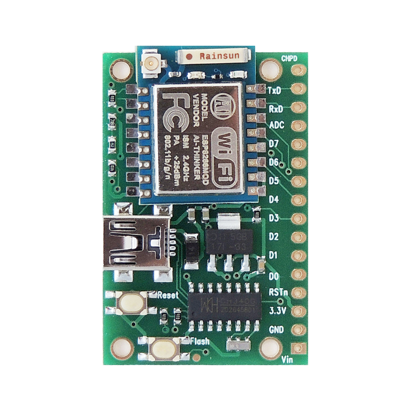
The ESP8266EX WiFi chip has taken the IoT market by storm. This board breaks out all the pins of the bigger ESP-07 module to 0.1" headers to allow easy breadbording and wiring. The board has 1k pull-up resistors on the CH_PD, IO0 and Reset signals to ensure that the board starts in normal operating mode. The ESP8266 draws a hefty 300mA when transmitting at full power and an on board 3.3V regulator supplies power to the module. The 3.3V is brought to connector pins to power external modules.
The current modules have 1M flash chips installed.
Each pin is clearly labeled and the pads are nice and big for easy soldering of the pins. The pins may be mounted from the top and bottom of the board to match your preference. There are four electrically isolated mounting holes for easy mounting.
On the top of the board the pins are labeled in accordance with the NodeMcu Lua interpreter's definitions and the back of the board has the default pin names. The Lua interpreter is highly recommended for fast results. See the 'New GPIO Map' section at this URL: https://github.com/nodemcu/nodemcu-firmware/wiki/nodemcu_api_en
Having the antenna on top of the breadboard screwed up the performance of the antenna hence the new design. The new design has a few more components than the first design. I included a USB to Serial converter on the board to make the board easier to use. I added a second switch to make it easier to start the integrated bootloader and I added a voltage divider to the ADC input pin. I also kept one of the best features of the previous design, its price!
The ESP8266 ADC has an input range of 0-1V and I added a divider to scale a 0-5V signal to the ADC input range.
The pinout was changed to make it easier to use the module on a breadboard or with perf board (Veroboard). All the signals are now on the one side of the module and appear on a sixteen pin 0.1" pitch header. It plugs into the very small breadboards leaving almost all the holes free and accessible.
The firmware of the ESP8266-07 module can easily be updated by pressing the Flash and Reset switches simultaneously and releasing the Reset switch before releasing the Flash switch. The on chip bootloader will then try to download new firmware from the serial port. The Flash switch can be used a user input if it is not pressed during Reset or power up.
The board is assembled on our pick and place machine and is reflow soldered.
The ESP8266-07 module and pins are included, the small breadboard is not included.
Under the downloads tab there are drawings of the board.